
Pickups, Wiring, and Color Codes
In light of Ryc's recent sticky thread about the plethora pickup questions and the same answers and links, I've put together this pickups and wiring thread to point folks to the common wiring diagram websites--the ones I go to for answers to your wiring questions:
http://www.ibanez.com/support/wiringdiagrams
http://www.guitarelectronics.com/category/wiring_resources_guitar_wiring_diagrams/
http://www.seymourduncan.com/support/wiring-diagrams/
http://www.guitarnucleus.com/schems.html
http://www.guitartechcraig.com/techwire/diagindx.htm
http://www.lennonstudios.com/pickup.html
***DiMarzio UPDATE***
DiMarzio's site has been revamped. Wiring diagrams are now available in the pickup's model page. This revamp is cool! You just click the pickup you want to see, scroll down the left side of the page to the link "Find the right wiring diagram for your guitar"--click it. Next, select the diagram you want. I love the fact that they included Ibanez specific diagrams right at the top. Click that, and you can go to model specific diagrams--way to go DiMarzio!
http://www.emgpickups.com/search/wiring
http://www.emgpickups.com/pdfs/faq/EMG-FAQ-Wiring-Questions.pdf
http://www.projectguitar.com/tut/pickupwiring.htm
JUST ADDED--***I've been telling folks about LonePhantom's "Taming the Tone Zone" mod when muddiness complaints come up. So, here's the link to his page where you can find the info and mod tutorial:
http://www.lonephantom.com/category/diy/pickups/
JUST ADDED --***Guitarheads Pickup Wiring info and diagrams***--see page 3/post #35
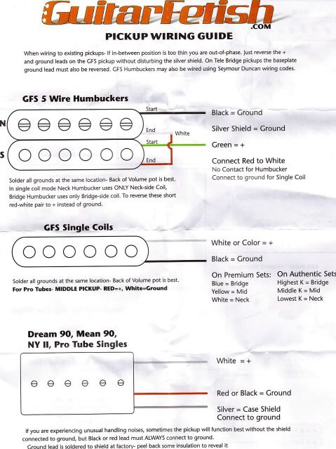
JUST ADDED--***GFS (Guitar Fetish) pickup wiring diagrams***--see page 3/post #36
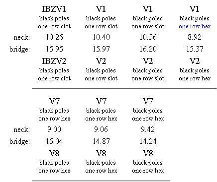
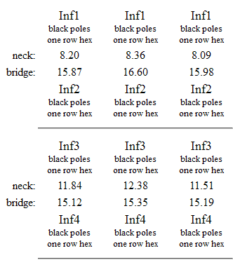
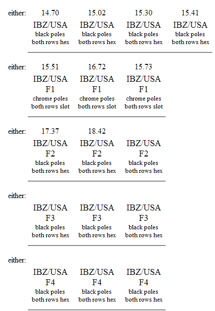
JUST ADDED--***Ibanez Pickups DC Resistance chart***--see page 3/post #37
JUST ADDED--***May11, 2011***--see page 3/post #38
I forgot that our good buddy Bancika has some great DIY stuff on his site! Here's the link to his Guitar Wiring 101 page:
http://diy-fever.com/misc/guitar-wiring-101/
Great stuff here, and info on wiring multipole switches, too.
JUST ADDED--***Aug 24, 2011***--see page 3 post #42
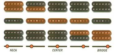
Our very own rickybaby1985 came up with some invaluable DiMarzio pickups output and EQ comparison charts--everyone give him a big thanks for taking the time to create these.
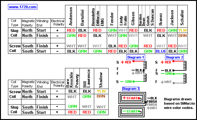
here are some pics of different pickup manufacturer's wire colors:
![Image]()
![Image]()
http://www.guitar-repairs.co.uk/guitar_pickup_colour_codes.htm
Here's some good info on soldering:
http://www.stewmac.com/freeinfo/Electronics/Pickup_building/w101-soldering.html
http://www.jag-stang.com/faq/general/how-do-i-wire-guitar-pickups/
http://www.colomar.com/Shavano/soldering.html
http://www.guitar-repairs.co.uk/guitar_wiring_modifications.htm
http://www.wikihow.com/Install-Guitar-Pickups
http://www.repairmyguitar.com/articles/03/23/how-to-solder-guitar-pickups/
Everything you ever wanted to know about potentiometers (pots):
http://sound.westhost.com/pots.htm
http://www.geofex.com/article_folders/potsecrets/potscret.htm
http://www.generalguitargadgets.com...ts.com/faq/40-technical-questions/174-what-does-pot-taper-mean-audio-log-linear
Adjusting pickup height:
http://www.projectguitar.com/tut/aph.htm
Here are some good resources for installing a killswitch:
http://www.instructables.com/id/Guitar-Killswitch-Strat.-design/
http://www.bigappleguitar.com/guitar-killswitch-wiring/
http://www.guitarelectronics.com/pr.../product/WIRING_MOD_SW001/Guitar-Wiring-Mod-Kill-Switch-Output-Mute-Switch.html
Other good wiring info:
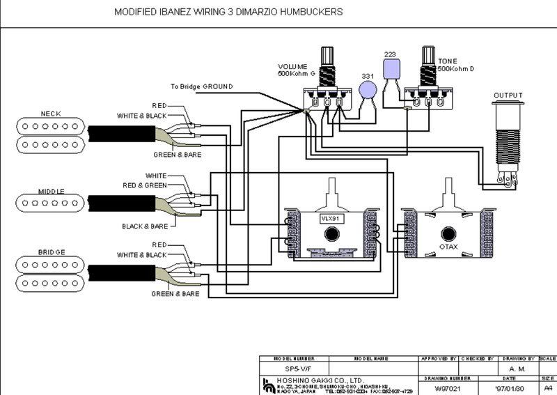
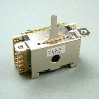
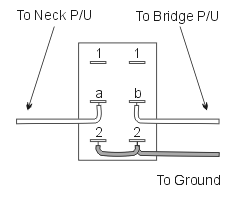
The diagram shows how to do this with a multipole 5-way (VLX91) Ibanez Part# 3PS1VLX91.
![Image]()
![Image]()
Quite a few Ibanez guitars will use a standard YM-50 5-way switch. It looks like this...
![Image]()
In order to have the switch work as it does with a standard middle single coil pickup, you need to replace the switch with Ibanez Part# 3PS1VLX91. It look like this...
![Image]()
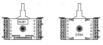
Here is the pin assignment for the VLX91, in case you want to know how the switch works with the wiring diagram.
![Image]()
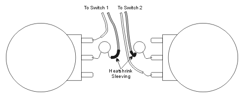
Common switch terminal connections added 04/14/2012
Please use this info as a guide before you start firing off, "Need help wiring my XXXXX."
In light of Ryc's recent sticky thread about the plethora pickup questions and the same answers and links, I've put together this pickups and wiring thread to point folks to the common wiring diagram websites--the ones I go to for answers to your wiring questions:
http://www.ibanez.com/support/wiringdiagrams
http://www.guitarelectronics.com/category/wiring_resources_guitar_wiring_diagrams/
http://www.seymourduncan.com/support/wiring-diagrams/
http://www.guitarnucleus.com/schems.html
http://www.guitartechcraig.com/techwire/diagindx.htm
http://www.lennonstudios.com/pickup.html
***DiMarzio UPDATE***
DiMarzio's site has been revamped. Wiring diagrams are now available in the pickup's model page. This revamp is cool! You just click the pickup you want to see, scroll down the left side of the page to the link "Find the right wiring diagram for your guitar"--click it. Next, select the diagram you want. I love the fact that they included Ibanez specific diagrams right at the top. Click that, and you can go to model specific diagrams--way to go DiMarzio!
http://www.emgpickups.com/search/wiring
http://www.emgpickups.com/pdfs/faq/EMG-FAQ-Wiring-Questions.pdf
http://www.projectguitar.com/tut/pickupwiring.htm
JUST ADDED--***I've been telling folks about LonePhantom's "Taming the Tone Zone" mod when muddiness complaints come up. So, here's the link to his page where you can find the info and mod tutorial:
http://www.lonephantom.com/category/diy/pickups/
JUST ADDED --***Guitarheads Pickup Wiring info and diagrams***--see page 3/post #35
JUST ADDED--***GFS (Guitar Fetish) pickup wiring diagrams***--see page 3/post #36
JUST ADDED--***Ibanez Pickups DC Resistance chart***--see page 3/post #37
JUST ADDED--***May11, 2011***--see page 3/post #38
I forgot that our good buddy Bancika has some great DIY stuff on his site! Here's the link to his Guitar Wiring 101 page:
http://diy-fever.com/misc/guitar-wiring-101/
Great stuff here, and info on wiring multipole switches, too.
JUST ADDED--***Aug 24, 2011***--see page 3 post #42
Our very own rickybaby1985 came up with some invaluable DiMarzio pickups output and EQ comparison charts--everyone give him a big thanks for taking the time to create these.
here are some pics of different pickup manufacturer's wire colors:

http://www.guitar-repairs.co.uk/guitar_pickup_colour_codes.htm
Here's some good info on soldering:
http://www.stewmac.com/freeinfo/Electronics/Pickup_building/w101-soldering.html
http://www.jag-stang.com/faq/general/how-do-i-wire-guitar-pickups/
http://www.colomar.com/Shavano/soldering.html
http://www.guitar-repairs.co.uk/guitar_wiring_modifications.htm
http://www.wikihow.com/Install-Guitar-Pickups
http://www.repairmyguitar.com/articles/03/23/how-to-solder-guitar-pickups/
Everything you ever wanted to know about potentiometers (pots):
http://sound.westhost.com/pots.htm
http://www.geofex.com/article_folders/potsecrets/potscret.htm
http://www.generalguitargadgets.com...ts.com/faq/40-technical-questions/174-what-does-pot-taper-mean-audio-log-linear
Adjusting pickup height:
http://www.projectguitar.com/tut/aph.htm
Here are some good resources for installing a killswitch:
http://www.instructables.com/id/Guitar-Killswitch-Strat.-design/
http://www.bigappleguitar.com/guitar-killswitch-wiring/
http://www.guitarelectronics.com/pr.../product/WIRING_MOD_SW001/Guitar-Wiring-Mod-Kill-Switch-Output-Mute-Switch.html
Other good wiring info:
The diagram shows how to do this with a multipole 5-way (VLX91) Ibanez Part# 3PS1VLX91.
Quite a few Ibanez guitars will use a standard YM-50 5-way switch. It looks like this...

In order to have the switch work as it does with a standard middle single coil pickup, you need to replace the switch with Ibanez Part# 3PS1VLX91. It look like this...
Here is the pin assignment for the VLX91, in case you want to know how the switch works with the wiring diagram.
Common switch terminal connections added 04/14/2012
Please use this info as a guide before you start firing off, "Need help wiring my XXXXX."


")